By David Cohn
Did you know that you can create animated walkthroughs directly in AutoCAD using features and functions that are included free as a standard part of the program?
Back in issue 18 of The Blast!, I wrote about how you can create beautiful photorealistic renderings of 3D AutoCAD models directly in AutoCAD, using features and functions that are included free as a standard part of the software. But did you know that you can also create animations?
That’s right. You don’t have to use 3ds Max, Maya, or some other program to create a walk-through or flythrough of your latest design in AutoCAD. Like the rendering tools, commands for creating animations are also included free with every copy of AutoCAD. And when the rendering and animation tools are combined, the resulting animations can also be photorealistic.
Unlike the rendering tools, the animation tools are not quite as easy to find. They are only available when working in a 3D modeling workspace, either 3D Modeling or 3D Basics. Like the rendering tools, the animation tools are found on the Visualize ribbon, but they are located in the Animations panel, which by default is not initially visible. So, the first thing you need to do is to turn on this panel. To do that, right-click any panel on the ribbon and then choose Show Panels > Animations from the shortcut menu.

To use AutoCAD’s animation tools, you must first enable the Animations panel on the Visualize ribbon.
Once you enable this panel, you will see several tools. There are basically two different ways to create animations in AutoCAD:
- You can interactively move around through a 3D model, recording as you go
- You can pre-define a path and then record the camera motion along that path
Recording Your Interactive Movements
To record your interactive movements, expand the small split button in the upper-right corner of the Animations panel. Here, you will find three tools: Walk, Fly, and Walk and Fly Settings. The Walk and Fly tools are quite similar. The only real difference is that when you use the Walk tool, the viewpoint of your animation only travels along the XY-plane, whereas when you use the Fly tool, this movement is not constrained, so the viewpoint can utilize the Z-axis as well, and appear to fly over an area of the model.

The Walk, Fly, and Walk and Fly Settings tools are all located in a small split button.
When you click the Walk tool, walk mode becomes active, and the program displays a Position Locator palette. By default, this palette shows your position in the drawing from a top view. You may also see a balloon notification in the InfoCenter with information about how to move around when using the Walk tool. It explains that you can use keys on the keyboard to move around within the viewport (using the arrow or W, A, S, D keys). You can also drag the mouse to change the direction in which you are looking, or use tools in the Position Locator palette itself.

When you start the Walk tool, your positon appears in the Position Locator palette and instructions appear in the InfoCenter.
The controls in the Walk and Fly Settings dialog can be used to adjust the default walk and fly settings. For example, you may want to change the Walk/Fly step size to 18 units, which is approximately the distance a person moves with each step.

Use the tools in the Walk and Fly Settings dialog to adjust the behavior of the Walk and Fly tools before capturing animations.
Once you have everything set properly and have experimented a bit with the Walk and Fly tools, you’ll be ready to capture your first animation. Adjust your 3D viewpoint so that you are viewing the model at the location you want to use as the starting point for your animation. Then, start the Walk tool again. This time, before you begin to move within the model, on the Animations panel, click the Record Animation button so that AutoCAD will record your movements. Now, start moving through the model.

Click Record Animation to begin recording your movements through the model.
Once you reach a stopping point, go back to the ribbon and click the Play button. The program opens an Animation Preview window, and you immediately see the animation that was recorded. As the animation plays, you can even change the visual style.
If you are satisfied with the animation, you can save it to a file. With the Animation Preview window open, click the Save button. If you close the Animation Preview window, there is also a Save button in the Animations panel.
When AutoCAD displays the Save As dialog, navigate to the folder in which you want to save the animation and assign a name. Although it initially appears that you can only save the animation as a WMV file, there are actually many more options, but again, they are hidden.
When you click the Animation settings… button, the program displays the Animation Settings dialog. Here, you have much more control over the resulting animation. For example, when you expand the Visual style drop-down, you can not only choose an available visual style, you can also choose Rendered, in which case AutoCAD will render each frame of the animation using the current render settings. In the Resolution drop-down, you can choose the resolution of the animation file. In the Format drop-down, you can choose the animation file type; you are not limited to just WMV. And in the Frame rate field, you can specify the number of frames per second to create in the finished animation. Just remember that if you render each frame of your animation and use the standard frame rate of 30 frames per second, it could take quite a while to produce the animation file. This is something best left to compute overnight.
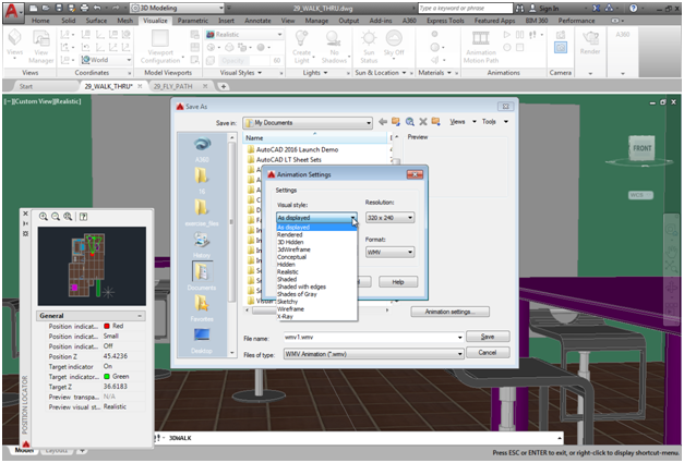
When you are ready to save your animation, the Animation Settings dialog lets you create a rendered animation and control various other settings.
Pre-Planning Your Path Through the Model
The Animation Motion Path tool records camera motion along a pre-defined path. This method enables you to plan your movement in advance.
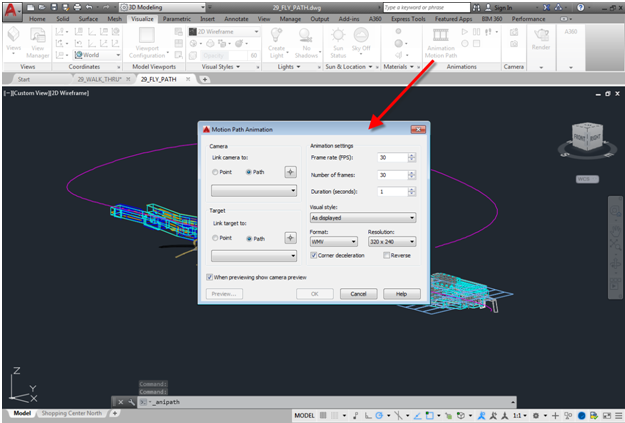
When you click the Animation Motion Path tool, the program displays the Motion Path Animation dialog.
When you start this tool, AutoCAD displays a Motion Path Animation dialog. You can use the controls in this dialog to specify a point or path for the camera and target, as well as the frame rate, number of frames, duration of the animation, visual style, animation file format, and resolution.
For example, to have the camera move along an existing spline path, in the Camera group box, you would select the Path radio button, and then select the path. You can also select a fixed target location or have the camera look along the path as it moves.
When you expand the Visual style drop-down, you can choose a predefined visual style or render each frame. Again, remember that if the animation is 30 seconds long, at 30 frames per second, it will contain 900 frames, each of which must be rendered individually, so you will likely want to let this run overnight.
There are several other tools that are not available when creating interactive walkthroughs. For example, the Corner deceleration option ensures that the camera moves a bit slower as it turns a corner, helping to prevent you from creating an animation that moves so quickly that it causes motion sickness. You can also reverse the direction of the animation. If you click the Preview… button, AutoCAD opens an Animation Preview window so that you can see a preview of the resulting animation.
Again, all the tools that I have described have been included in AutoCAD for years. Now that you know how to find and use them, what are you waiting for?
